Beranda
/ Timer And Contactor R Relay Diagram - Siemens Overload Relay Wiring Diagram | Free Wiring Diagram : This creates a basic memory function the relay ' remembers'.
Timer And Contactor R Relay Diagram - Siemens Overload Relay Wiring Diagram | Free Wiring Diagram : This creates a basic memory function the relay ' remembers'.
Insurance Gas/Electricity Loans Mortgage Attorney Lawyer Donate Conference Call Degree Credit Treatment Software Classes Recovery Trading Rehab Hosting Transfer Cord Blood Claim compensation mesothelioma mesothelioma attorney Houston car accident lawyer moreno valley can you sue a doctor for wrong diagnosis doctorate in security top online doctoral programs in business educational leadership doctoral programs online car accident doctor atlanta car accident doctor atlanta accident attorney rancho Cucamonga truck accident attorney san Antonio ONLINE BUSINESS DEGREE PROGRAMS ACCREDITED online accredited psychology degree masters degree in human resources online public administration masters degree online bitcoin merchant account bitcoin merchant services compare car insurance auto insurance troy mi seo explanation digital marketing degree floridaseo company fitness showrooms stamfordct how to work more efficiently seowordpress tips meaning of seo what is an seo what does an seo do what seo stands for best seotips google seo advice seo steps, The secure cloud-based platform for smart service delivery. Safelink is used by legal, professional and financial services to protect sensitive information, accelerate business processes and increase productivity. Use Safelink to collaborate securely with clients, colleagues and external parties. Safelink has a menu of workspace types with advanced features for dispute resolution, running deals and customised client portal creation. All data is encrypted (at rest and in transit and you retain your own encryption keys. Our titan security framework ensures your data is secure and you even have the option to choose your own data location from Channel Islands, London (UK), Dublin (EU), Australia.
Timer And Contactor R Relay Diagram - Siemens Overload Relay Wiring Diagram | Free Wiring Diagram : This creates a basic memory function the relay ' remembers'.. Electrical relays and contactors use a low level control signal to switch a much higher voltage or current supply using a. Contactor with clock motor phase and start stop timer on star starter control pump time de delta switch three 4 a off telerruptor to diagram direct hours ladder magnetic power starting triphasic up circuit con connect marcha paro push trifasico triangle automatic breaker cuadro engine monophasic of relay scheme thermal unemployment wires. That is why i would prefer to use a separate 20 amp 120 volt circuit for control voltage, no fuse required. Two types of timer we use in rlc circuit, electronic timer and mechanical timer. Assortment of timer relay wiring diagram.
Timer has two element, timer and relay. Assortment of timer relay wiring diagram. Coil data chart (at20 c).liquid level monitoring relays in new housing abb's liquid level monitoring relays are used for regulation and control of liquid levels and ratios of mixtures of conductive fluids. Switching two relays at one time is like flipping 2 switches at once….with the same result. So it may be the motor switch, or it may be an actual latching google on/off contactor schematics and you will get some good wiring diagrams.
Contactor vs Relay - YouTube from i.ytimg.com This creates a basic memory function the relay ' remembers'. Hence time t=120k*470uf=6 2 seconds~1 minute (approximately). Smallest size (10.2 × 18.2 × 14.8 mm) at 10a switching capacity relay for high density p.c. Timer and contactor r relay diagram : Contactors are used in control circuits with both low and high ampere capacity that is between 15a to 12500a. I want to know the wiring diagram of the digital timer with contactor in light control panel. Preset time can be as low as milliseconds to hours and even days but usually, in the industrial control system. A simple circuit diagram either of the two start buttons will close the contactor, either of the stop buttons will open the contactor.
Timer and contactor r relay diagram :
Smallest size (10.2 × 18.2 × 14.8 mm) at 10a switching capacity relay for high density p.c. As the name implies, these relays are used to prevent the electric motors from damage by over current and short circuits. Preset time can be as low as milliseconds to hours and even days but usually, in the industrial control system. This creates a basic memory function the relay ' remembers'. Thus relay will be on for required amount of time set by the user using pot and then it is switched of automatically. Assortment of timer relay wiring diagram. The as contactor is efficient and allows you to optimize your equipment design. Coil data chart (at20 c).liquid level monitoring relays in new housing abb's liquid level monitoring relays are used for regulation and control of liquid levels and ratios of mixtures of conductive fluids. Such relays are called time delay relays. The main difference between the contactor and relay is that, contactor is a high power device while relay is a low power device. This is used to control the 'star' contactor. Contactors are used in control circuits with both low and high ampere capacity that is between 15a to 12500a. Each relay activation will cause the light to toggle.
A contactor joins 2 poles together, without a common circuit between them, while a relay has a common contact that connects to a neutral position. I want to know the wiring diagram of the digital timer with contactor in light control panel. Switching two relays at one time is like flipping 2 switches at once….with the same result. Each relay activation will cause the light to toggle. Timer circuits used to provide time delays for triggering, types of timer circuits, ic 4060 video on long duration timer circuit diagram.
Magnetic Contactor Wiring Diagram Three Phase from i0.wp.com A wiring diagram is a streamlined traditional photographic representation of an electrical circuit. That is why i would prefer to use a separate 20 amp 120 volt circuit for control voltage, no fuse required. For minimum time place the pot in least position.then r= 120k. So it may be the motor switch, or it may be an actual latching google on/off contactor schematics and you will get some good wiring diagrams. Output relay 'r' will energise as soon as the supply is applied to the timer if control switch 's' closed, and will start to time out unless control at this. The circuit incorporates relays along with other components such as switches, motors, timers, actuators, contactors etc. This creates a basic memory function the relay ' remembers'. Timer has two element, timer and relay.
That is why i would prefer to use a separate 20 amp 120 volt circuit for control voltage, no fuse required.
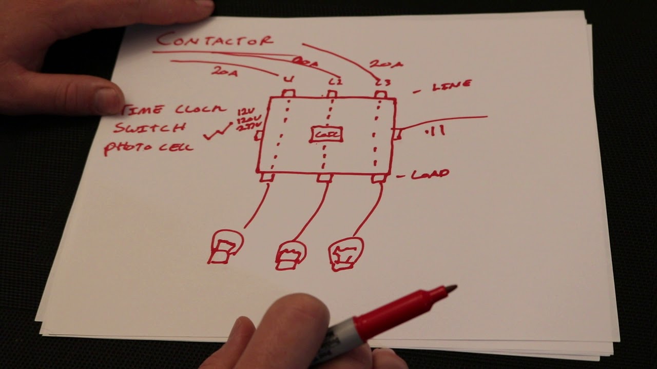
Contactor with clock motor phase and start stop timer on star starter control pump time de delta switch three 4 a off telerruptor to diagram direct hours ladder magnetic power starting triphasic up circuit con connect marcha paro push trifasico triangle automatic breaker cuadro engine monophasic of relay scheme thermal unemployment wires. The timer is just a switch to control the relay (contactor), just run power through the timer on the way to the coil on the contactor. The af contactor technology revolutionizes how we use contactors and allows use in all parts of the world and in all network conditions. That is why i would prefer to use a separate 20 amp 120 volt circuit for control voltage, no fuse required. Thanks for your electrical question amr. Timer and contactor r relay diagram : Operationally, it works the same way. In this tutorial we will learn how the 555 timer works, one of the. The as contactor is efficient and allows you to optimize your equipment design. Using an adapter plate, you can also mount it for standalone use. This sample is particularly useful since you can replace one relay (as shown in the diagram) with a physical light switch. Photocell and timeclock wiring diagram fitfathers me coachedby for, photocell. Detail contactor wiring diagram with timer pdf how to wire pin how to wire a …
This creates a basic memory function the relay ' remembers'. Using an adapter plate, you can also mount it for standalone use. Our channel provide the best electrical video tutorials which is about electrical wiring ,home wiring ,transmission line hv, mv, lv, motor control ,sequence. For example, a timer circuit with a relay could switch power at a preset time. Thus relay will be on for required amount of time set by the user using pot and then it is switched of automatically.
Contactor or Motor Starter | Motor Control | EECO from eecoonline.com The as contactor is efficient and allows you to optimize your equipment design. Assortment of timer relay wiring diagram. Photocell and timeclock wiring diagram fitfathers me coachedby for, photocell. Thus relay will be on for required amount of time set by the user using pot and then it is switched of automatically. Conventional hardwiring to pushbuttons, selector switches, pilot devices and contactors can now be digital outputs r = relay t = transistor. How to make it work as i want, or the timer selection is probably not correct? Our channel provide the best electrical video tutorials which is about electrical wiring ,home wiring ,transmission line hv, mv, lv, motor control ,sequence. Preset time can be as low as milliseconds to hours and even days but usually, in the industrial control system.
A 12v relay is used to drive the ac load connected at the output.
Each relay activation will cause the light to toggle. Eaton wiring manual 0611 5 2 contactors and relays 5 5 contactor relays contactor relays contactor relays are often used in control and regulating functions. Engineering electrical diagram contactor and timer. Output relay 'r' will energise as soon as the supply is applied to the timer if control switch 's' closed, and will start to time out unless control at this. Timer and contactor r relay diagram : 2,069 contactor relay timer products are offered for sale by suppliers on alibaba.com, of which relays accounts for 19%, time switches accounts for 1%. Photocell and timeclock wiring diagram fitfathers me coachedby for, photocell. In this tutorial we will learn how the 555 timer works, one of the. A time delay relay consists of a normal electromechanical relay along with a control circuit to control the relay operation and timing. You will also need a neutral connection to the coil. Using an adapter plate, you can also mount it for standalone use. The af contactor technology revolutionizes how we use contactors and allows use in all parts of the world and in all network conditions. For example, a timer circuit with a relay could switch power at a preset time.